The Faroudja VP400A Video Processor is a precision video instrument used to convert NTSC Composite, Y/C, or 525 line RGB or Component interlaced signals into 1050 line progressive outputs. Using the VP400A Video Processor will produce pictures with more details, remove unwanted picture artifacts and, when used with projection systems, produce pictures of exceptional quality, giving a "cinema-like" feeling.
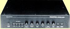
Front panel features include Power, Input Select (Video, Y/C, RGB and Component), Brightness, Contrast, Color, Auto-Tint, Noise Reduction, Detail, Digital Filter and Freeze. Input switch settings are memorized when the power is removed from the unit. This allows the VP400A to be interfaced into a system without the need to select the input when the system is powered up. The remaining controls may be left in factory preset or manually set by pulling out and rotating the control until the desired level is established.
Inputs to the VP400A include: Composite Video, Y/C (S-VHS), RGB and Component (Y,R-Y,B-Y). The Video input may be connected by either a BNC connection or a video RCA type connection. These inputs are looped internally so that the signal may be used by other devices. A selectable 75 Ohm terminator switch is provided and should be in the ON position if the input loop is not used. The Y/C input uses a standard 4 pin S-VHS connector. This input is not available for a looped operation and is terminated internally. The RGB and Component inputs use BNC connectors. As with the video input, these inputs are loopable to other devices. Selectable 75 Ohm terminations are provided. If the looped inputs are used, these cables should be kept short, (under 6' in length) or a video distribution amplifier should be used. This allows the VP400A to keep the highest signal bandwidth possible without having the high frequency being attenuated in a long cable.
Output from the VP400A is provided on six BNC connectors as well as one 15 pin 'D' connector. The BNC outputs provided are Red, Green, Blue, Horizontal Sync, Vertical Sync and Composite Sync. Interface to monitors/projectors can be of a 4 or 5 wire connection. Note: 4 wire, meaning Red, Green, Blue and Composite Sync or 5 wire, meaning Red, Green, Blue, Horizontal Sync and Vertical Sync. There is no sync present on the Green output. The VP400A is capable of driving a monitor/projector using the BNC outputs as well as a 15 pin 'D' connector, at the same time. The monitor and projector have to scan at 62.94KHz Horizontal scan rate. The VP400A features a RS-232 remote control interface that will allow control of all line quadrupler functions. The remote control uses a 25 pin female 'D' connector located on the rear panel.
Circuit Description
Figure 1 is a block diagram of the VP400A showing signal flow and the location of front panel controls and switches. Composite Video and Y/C (S-VHS) inputs are connected to the units decoder with AGC control and converted to Y, R-Y and B-Y signals. The Y, (Luminance) output from the decoder enters the input switcher while the R-Y and B-Y signal enter the Chroma Enhancement block where the Tint phase can be adjusted when selected in the manual mode. The RGB input signals are transcoded to Y, R-Y, and B-Y signals and fed to the input switcher. Component signals are fed directly to the input switcher. The input switcher then selects the correct function and outputs the Y signal to the Luminance Line Quadrupler block. The Luminance Line Quadrupler block contains the Brightness, Contrast and Freeze controls while the R-Y and B-Y signals enter the Chroma Line Quadrupler block where the color level can be controlled along with the Freeze controls. The Line Quadrupled Luminance signal now enters the Luminance Detail and Noise Reduction block where the functions of Noise Reduction and Detail Level are controlled.
The Luminance signal from the Luminance Detail and Noise Reduction block along with the R-Y and B-Y signals from the Chroma Line Quadrupling block feed the output transcoder and are converted to RGB signals. These RGB signals are buffered and then sent to the rear panel outputs to both the BNC and monitor interface connectors. When using the RGB or Component inputs, Sync is derived from the G or Y input signals unless sync is provided to the Composite Sync input. The Composite Sync input will override the sync from the G or Y inputs. The sync signal then feeds the VP400A systems clock generator and is used as a reference to generate Horizontal Sync, Vertical Sync and Composite Sync.
| © 1997 American Hi Definition, Inc. | A-Z Index |
| Go Back to Our Main Page | Search Our Site |